About 66 minutes
Lecture on Artificial Flight Given by request at the Academy of Natural Sciences — Reading Notes
Mechanical Engineering
15,173 recorded words. 1 minutes difference from this book's estimate.
View Gutenberg source #38109
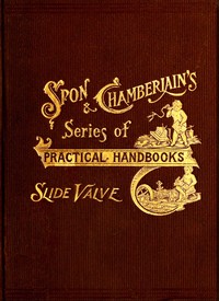
This digital edition of The slide valve, simply explained — Text and Context is described by source-level measurements including 15,376 words, 1 hr 7 min estimated reading time, and 3 detected text sections.
The text analysis averages about 26.5 words per sentence, while the detected sections provide another way to judge how the source is divided.
Project Gutenberg metadata also associates the work with “Slide-valves,” connecting these edition facts with the source record’s subject description.
Explore this collection
These alternatives are selected using recorded categories and estimated reading time.
About 66 minutes
Mechanical Engineering
15,173 recorded words. 1 minutes difference from this book's estimate.
View Gutenberg source #38109About 58 minutes
Mechanical Engineering
13,278 recorded words. 9 minutes difference from this book's estimate.
View Gutenberg source #29934About 55 minutes
Mechanical Engineering
12,600 recorded words. 12 minutes difference from this book's estimate.
View Gutenberg source #48360Search stored excerpts and compare books → Choose by your preferences →
Choices use stored catalog measurements. Estimates vary with reading speed. A shared category is a catalog label, not a claim that two books have the same argument or literary quality.
Search reads excerpt text stored with this catalog and links to its associated Gutenberg record. The connection is stored in the site database; this tool does not recheck that every excerpt is word-for-word identical to that external record. Excerpt search does not cover every chapter and does not verify historical publication dates.
Catalog snapshot checked: 2026-09-26. Coverage: 91 public books, 91 available source excerpts.
Calculated from edition completeness, EPUB availability, text structure and catalogue metadata. Not a user rating.
Total of 100 points, scaled to a 2.5-5.0 range. Editions with an empty description or a missing EPUB file are not scored.
Public-domain source text
The source text is kept in the dedicated reader, separate from this catalogue record and its commentary.
This 1899 manual, revised and enlarged by J. H. Kinealy, originated as notes to help railway students grasp slide valve operation. Rather than relying solely on a large sectional model engine, the author devised a personal, portable model: a rotary disc representing the crank-shaft, with a crank-arm as an index finger to trace concentric circular diagrams. The method deliberately eliminates the eccentric and its rod, instead correlating valve and crank-shaft movements through adjacent scales, requiring step-by-step adjustment—a feature the writer found advantageous for comprehension.
The preface reveals a deliberate pedagogical shift: the author wanted results that were “not merely qualitative, but also, in some degree, quantitative.” The rotary disc model allowed students to record the beginnings and ends of arcs swept by the crank during distribution periods, enabling direct comparison of valve actions under varying conditions. This emphasis on measurable, graphical output—exemplified by figures like fig. 21—distinguishes the work from purely descriptive treatments. The diagrams are not illustrations but working tools, meant to be cogitated upon and used for comparison.
The text repeatedly addresses the problem of friction between the valve and its seat. It describes how ordinary flat slide valves suffer from unbalanced steam pressure on the back, creating considerable friction. Solutions are presented through specific valve designs: the balanced flat valve uses a cover plate and distance pieces to create a steam-tight joint without pressing the valve against the seat; piston valves eliminate the pressure surface entirely by making port-faces cylindrical. The discussion of internal versus external steam supply further shows how valve orientation and eccentric setting must be reversed—by 180 degrees—to maintain proper timing.
Concrete setting instructions appear throughout. For the straight line valve, the linear advance must equal steam lap plus one-half the desired lead; travel is twice the sum of steam lap and half the maximum port opening. For a quadruple admission valve like the Woodbury, the formula changes: travel equals twice the sum of steam lap and one-fourth the maximum opening. These precise numerical relationships, tied to specific valve types, show the manual’s practical bent. The text also notes that multiple admission valves differ from ordinary ones only in the suddenness of port opening and closing—a subtle but critical distinction for timing.
Readers should approach this work with a pencil and paper at hand, ready to trace the diagrams and work through the step-by-step adjustments described. The model is meant to be built mentally if not physically, and the quantitative approach rewards careful study of the figures. The manual’s value lies not in sweeping theory but in the precise, repeatable methods it offers for understanding valve motion—methods that remain instructive for anyone learning steam engine mechanics.
Years handling the 1899 slide valve manual, I came to love its patient diagrams—each turning disc a quiet lesson in adjustment. That same unhurried care lives in Flat Machine Knitting and Fabrics — Inside the Classic, where loops and rows unfold like familiar stitches. Both books whisper of hands finding their way by feel, not fuss.
Use these questions to collect your thoughts before moving on.